
I have always wanted to own my own arcade. I have been playing around with the Raspberry Pi since the first model came out back in 2012. Once I saw the performance of the pi 2, I knew it was time to build a custom arcade. I started this project in July of 2015 and finished this build back in November 2015, but have not had a chance to put together an article. I will soon be upgrading the pi in my arcade to the Raspberry pi 3.
I had based my build off of the following article. I chose that article because it was one of the best 2 player setups I had seen. Below is a brief overview of the parts and the software that I used. Items I used to build my Arcade
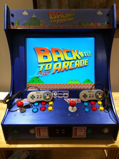
- The Cabinet is constructed from 3/4 MDF (I will upload real size PDF cad drawings soon)
- Clear Acrylic (I used 2 pieces and sandwiched the banner between them. I would use quarter-inch or half-inch)
- I got the banner printed on special transparency paper. (You can get this done at most print shops)
- 1 x Raspberry Pi 2 (Will soon be upgrading to Raspberry Pi 3)
- 1 x Micro USB power supply. (Any Micro USB power supply over 2 amps will work fine; however, I do recommend the one from CanaKit)
- 1 x 32GB Micro SD card (Get a good name brand card to prevent issues)
- Raspberry Pi Case with Heatsinks (Do you really need heatsinks? Probably not, but it came with a case I had bought so why not. I recommend not putting the lid on the case – I left it open as you can see in the pictures below.)
- Optional USB WiFi Adapter. (list of working Adapters. I went with the TP-Link, seems to work the best.)
- 12 inch LED strip light for behind the banner. (I went to a local shop and got a 12-inch strip, but that deal from amazon is way better.)
- AdaFruit 30mm Buttons (Note this is for the red button, but they have a variety of colors. Personally, I would recommend purchasing higher quality buttons – I was so eager to build the arcade that I didn’t do to much research on buttons.)
- AdaFruit Small Joystick (Similarly to the buttons, you might want to look at getting a higher quality joystick as well.)
- Female to Female jumper cables (One end went to the GPIO pins on the Raspberry Pi, the other end I cut off and put on a quick connect spade connector to connect to the arcade buttons and joystick)
- 4 port keystone wall plate with 4 USB keystones for optional controller usage. These can be purchased from a number of sites. (USA store / Canadian store)
- 4 x 1ft USB A Male to A Male (Again, these can be purchased at a variety of places.)
- Optional 2 port keystone wall plate for the back of the arcade with a 1 x HDMI keystone and 1 x Ethernet keystone. (The HDMI is useful if you want to output the arcade to a big screen TV. The Ethernet is useful if you want to plug it into your router to do updates instead of using a WiFi Adapter.)
- 1 x Power bar (However many ports you need – I got one with 6)
- 1 x Power Entry Module. You can also find ones with inline fuses as well. (cut off the end of the power bar and wire it up to the Power Entry Module. That way, you have a removable plug for your arcade with a main switch.)
- 20 inch 4:3 LCD monitor with DVI input (I chose 4:3 to make it very authentic. Remember to make sure it has DVI!)
- 1 x DIV to HDMI cable
- Logitech Z130 powered speakers
- Various Decals ordered from RedBubble (Honestly the best quality stickers I have ever purchased. Also, they have a great selection and you can upload your own designs)
- Buffalo Classic SNES USB Controller (I ordered a few different ones – this one works the best and feels just like the original, although it is a tad thicker.)
CAD Files!
I have finally had sometime to make the adjustments needed to the CAD files. Below are links to the CAD files and also PDF versions so you can Print them out on a Plotter. There are 2 CAD files one with the Arcade and one for the Controls (I have zipped them)
Software I used
- RetroPie Project – I tried a few of the other distributions, however, I found this one to be the best. They provide timely updates and the forums have a lot of support.
- I chose not to use a USB interface to wire the control to. I used the Raspberry Pi’s GPIO pins and there is no delay whatsoever.
- To setup the GPIO pins with the controls, I used the this article. I made some modifications, but once you play around with it, you will see how the config files work.
- There is a variety of ROM’s available all over the internet. With the Pi 2, I was able to get the following Emulators working perfectly.
- NES
- SNES
- Nintendo 64 (Lags a bit, however, the Pi 3 seems to fix this issue)
- Mame
- Atari 5200
- Atari 7800
- PC Dos
- Sega Genies
- Sega Master System
- Game Boy
- Game Boy Colour
- Game Boy Advance
I will keep this article updated so keep this page bookmarked.

Any cad files yet? 🙂
Yes! Flip me an email on the contact us page
yup check the post again i have added them
Hi, can you send me the cad files please?
Thanks
Cheers
Julien
added to the page!
hi
Can you sell me a box without the rasperry ?